Overview:
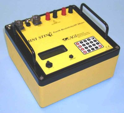
The MiniSting and Sting are single channel, soil resistivity meters designed for ease of use. Both units possess a rugged design built to withstand the harshest of conditions. The software is menu driven with tactile buttons that are easy and intuitive to use. An internal memory stores results, allowing a user wants to transfer the information to a computer and use AGI’s processing software, Earthimager, to process. The Ministing, a newer model, possesses a built-in rechargeable NiMH battery whereas the Sting, a slightly older design, has a removable NiMH battery pack- both are capable of performing manual resistivity tests for a full work day.
There are nine preprogrammed manual resistivity tests: Wenner, Schlumberger, Dipole-Dipole, Pole-Dipole, Pole-Pole, Mise-A-La-Masse, Self-Potential (SP), Resistance, and Azimuthal. Further, they are both capable of induced polarization testing. The MiniSting and Sting are commonly used for vertical electrical soundings (VES,) performing the IEEE Fall-Off-Potential (FOP) method, four-pin wenner soil tests (ASTM G57,) groundwater investigations, cathodic protection designs, and other grounding studies.
Configuration and Considerations
Besides housing and battery packs, the MiniSting and Sting are virtually identical. Therefore, there is little need for a user to select one over another. For surveys with very large electrode spacings, a more powerful meter such as a SuperSting may be needed. However, in general, the MiniSting and Sting can perform most 4 pin resistivity surveys.
The user would be more apt to focus on meeting survey design and site parameters. For instance, if performing a Wenner array, the user wants to make sure they have large enough spools of wire to meet the maximum A-spacing of the survey. Although large spools will meet most tasks, an appropriate sized spool makes it easier for the field help to carry. A survey runs very smoothly with a team of 3 people: One operator controlling the meter and two field workers each moving two spools. Another consideration is the ground in which the electrodes are inserted. A 3lb hammer and even a drill with a large bit may be necessary for very hard ground in order to insert the electrodes into the ground. Likewise, a bit of water may be needed for very dry or frozen ground at each point source to make better contact with the subsurface.
Typical MiniSting/Sting Packing List
1 x MiniSting R1 or Sting R1 Console
1 x Cable (Computer to Sting Console)
1 x Battery Charger
1 x Cable (Sting Console to External 12 Volt Battery)
1 x Calibration Cable
1 x USB Flash Drive with Software and Manuals
2 x Current Cable on Plastic Reels
2 x Potential Cable on Plastic Reel
5 x Jumper cable 1.8 m (Cable Reels to Electrodes)
5 x Stainless Steel Electrodes
1 x Shipping Case (24x20x10, 35lbs)
1 x Shipping Case for Spools (22 x 15 x 12, 40lbs) ***dimensions depend on spool size
User Manuals
MiniSting Specifications
Measurement modes: Apparent resistivity, resistance, voltage (SP), induced polarization (IP), battery voltage
Measurement range:
400 kn to 0.1 millin (resistance)
0-500 V full scale voltage autoranging.
Measuring resolution: Max 30 nV, depends on voltage level
Screen resolution: 4 digits in engineering notation
Output current: 1-2-5-10-20-50-100-200-500 rnA.
Output voltage: The user can switch between high and low voltage limit for the transmitter (800 Vp-p or 320 Vp-p voltage limit). Actual electrode voltage depends on transmitted current and ground resistivity.
Input gain ranging: Automatic, always uses full dynamic range of receiver.
Input impedance: >20Mn
Input voltage: Max 500 V
SP compensation: Automatic cancellation of SP voltages during resistivity measurement. Constant and linearly varying
SP cancels completely.
Type of IP measurement: Time domain chargeabilitiy (M), six time slots measured and stored in memory
IP current transmission: ON+, OFF, ON-, OFF
IP time cycles: 1 s. 2 s, 4 s and 8 s
Measure cycles: Running average of measurement displayed after each cycle. Automatic cycle stop when reading errors fall below user set limit or user set max cycles are done.
Cycle time: Basic measure time is 1.2, 3.6, 7.2 or 14.4 s as selected by user via keyboard. auto ranging and commutation adds about 1.4 s.
Signal processing: Continuous averaging after each complete cycle. Noise errors calculated and displayed as percentage of reading. Reading displayed as resistance (dV/1) and apparent resistivity (nm).
Resistivity is calculated using user entered electrode array coordinates.
Noise suppression:
Better than 100 dB at f>20 Hz
Better than 120 dB at power line frequencies (16 2/3, 20, 50 and 60Hz).
Total accuracy: Better than 1% of reading in most cases (lab measurements). Field measurement accuracy depends on ground noise and resistivity. Instrument will calculate and display running estimate of
measuring accuracy.
System calibration: Calibration is done digitally by the microprocessor based on correction values stored in memory.
Supported configurations: Resistance, Schlumberger, Wenner, dipole-dipole, pole-dipole, pole-pole, azimuthal, mise-a-lamasse, SP (absolute) and SP (gradient).
Data storage: Full resolution reading average and error are stored along with user entered coordinates and time of day for each measurement. Storage is effected automatically.
Memory capacity: More than 3000 measuring points can be stored in internal memory.
Data transmission: RS-232C channel included to dump data from instrument to PC on user command.
Automatic multi-electrodes: The MiniSting is designed to run dipole-dipole surveys completely automatic with the optional Swift
Dual Mode Automatic Multi-electrode system (patent 6,404,203). The MiniSting/Swift can run any
other array (Schlumberger, Wenner etc.) by using special user programmed command files. These
files are created in an MS DOS type computer and downloaded to the MiniSting RAM memory and
are later recalled and run in the field. Therefore there is no need for a fragile computer in the field.
User controls: 20 key tactile, weather proof keyboard with numeric entry keys and function keys.
On/off switch r
Measure button, integrated within main keyboard.
LCD night light switch (push to light).
Display: Alphanumeric LCD display (4 lines x 20 characters) with night light.
Connectors: 4 banana plug, pole screws for current and potential electrodes. 3-pole KPT connector for external
power, 1 0-pole KPT connector for RS-232C and synchronization connections.
Power supply: 12V, 4.5 Ah NiMH built-in rechargeable battery. External power connector on front panel, the
instrument automatically selects external battery if present.
Operating time: Depends on conditions, internal circuitry in auto mode adjusts current to save energy. At 20 rnA
output current and 10 kn electrode resistance more than 2000 cycles are available from a fully
charged battery pack.
Battery charger: Dual stage charger with switchable input (115/230 V AC @ 50/60 cycles)
Weight: 6.6 kg (14.5 lb.)
Dimensions: Width 255 mm (10″), length 255 mm (10″) and height 123 mm (5″)
Sting Specifications
Measurement modes: Apparent resistivity, resistance, voltage, battery voltage
Measurement ranges: 400 kohms to 0.1 milliohm (resistance) 0-500 V full scale autoranging (voltage)
Measuring resolution: max 30 nV, depends on voltage level
Screen resolution: 4 digits in engineering notation.
Output current: 1-2-5-10-20-50-100-200-500 mA,
Output voltage: The user can switch between high and low voltage limit for the transmitter (800 Vp-p or 320 Vp-p voltage limit). Actual electrode voltage depends on transmitted current and ground resistivity. Instrument always starts up in low voltage setting.
Input gain ranging: Automatic, always uses full dynamic range of receiver.
Input impedance: >20 Mohms
Input voltage: Max 500 V
SP compensation: Automatic cancellation of SP voltages during resistivity measurement. Constant and linearly varying SP cancels completely.
Measure cycles: Running average of measurement displayed after each cycle. Automatic cycle stops when reading errors fall below user set limit or user set max cycles are done.
Cycle time: Basic measure time is 1.2, 3.6, 7.2 or 14.4 s as selected by user via keyboard. Autoranging and commutation adds about 1.4 s.
Signal processing: Continuous averaging after each complete cycle. Noise errors calculated and displayed as percentage of reading.Reading displayed as resistance (V/I) and apparent resistivity (m or ft). Resistivity is calculated using user entered electrode distances.
Noise suppression: better than 100 dB at f>20 Hz better than 120 dB at power line frequencies (16 2/3, 20, 50 & 60 Hz)
Total accuracy: Better than 1% of reading in most cases (lab measurements). Field measurement accuracy depends on ground noise and resistivity. Instrument will calculate and display running estimate of measuring accuracy.
System calibration: Calibration is done digitally by the microprocessor based on correction values stored in memory. The correction values are found in final production testing and are also established during later periodical recommended yearly checks at authorized service centers.
Data storage: Full resolution reading average and error are stored along with user entered coordinates and time of day for each measurement. Storage is automatic.
Memory capacity: Over 3000 measuring points can be stored in the internal memory.
Data transmission: RS-232C channel available to dump data from instrument to PC computer on user command. PC program supplied with instrument.
Communication setting: 4800 baud, 8 data bits, no parity, 1 stop bit
User controls: 20 key tactile, weather proof keyboard with numeric entry keys and function keys.
ON/OFF switch.
MEASURE button integrated within main keyboard.
LCD contrast adjustment.
LCD night light switch (push to light)
Display: Alphanumeric LCD display (4 lines x 20 characters). Used for display of results and menus. Night light by LED backlight panel available on switch operation.
Connectors: 4 banana plug pole screws for current and potential electrodes.
10-pole KPT connector for external power, charge, RS-232 and synch connections.
KPT connector signals:
A Transmit RS-232 data
B Battery (-)
C Battery (+)
D –
E +5V supply out for external units
F Receive RS-232 data
G Signal ground
H Synchronization input and remote start
J –
K Synchronization output
Power supply: 12 V, 5 Ah NiCd rechargeable snap-on battery. External power connector on front panel, the instrument automatically selects external battery if present.
Operating time: Depends on conditions. At 20 mA output current and 10 kΩ electrode resistance more than 2000 cycles are available from a fully charged battery pack.
Battery charger: Dual stage charger with switchable input (115/230 V AC @ 50/60 cycles).
Instrument dimensions: Width 112 mm (4.4″), length 293 mm (11.54″) and height 308 mm (112.11″).
Instrument weight: 6.6 kg (14.5 lb) including snap-on battery pack.